Mass Air Flow (MAF) Sensors
It is important for a Technician to identify the type of MAF sensor fitted to the vehicle and carry out the appropriate test procedure if it is suspected of being faulty.
| There are generally two categories: |
Analogue MAF – Varying voltage output Digital MAF – Frequency output. |
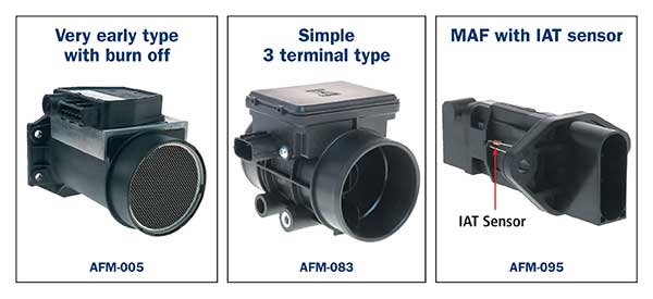
Analogue MAF Sensor
These units range from a simple (minimum) 3 terminal sensor for measuring air flow only, to a multiple
connector sensor that integrates an intake air temp sensor and on some very early types a burn off circuit to clean the sensing wire. (Hot wire)
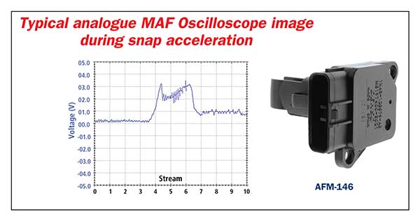
Analogue MAF signal.
Voltage output varies with air flow. Note: Generally low voltage output with low air quantity and increased voltage output as air flow increases.
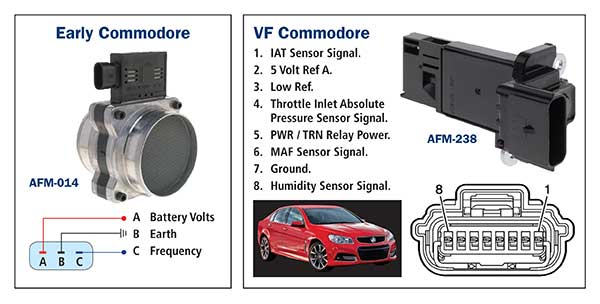
Digital MAF sensor.
These units also range from a simple (minimum) 3 terminal sensor monitoring air flow only, to a comprehensive 8 terminal MAF unit for monitoring not only air flow but also including pressure, temperature and humidity.
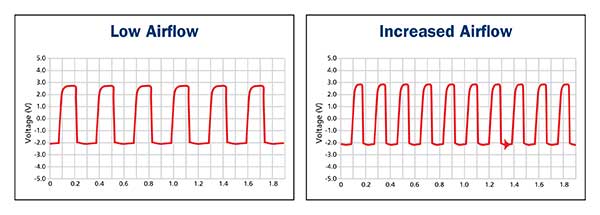
Digital MAF signal.
Frequency output varies with air flow. Note: Generally low frequency output with low air quantity and increased frequency output as air flow increases.
Typical MAF sensor faults and effects on the vehicle performance.
- Low output signal.
- Will generally result in lean mixtures and driveability problems. Note: there are many other engine systems that can create lean mixtures and it is important to correctly determine if the MAF is the cause.
- Internal MAF circuit faults.
- Internal circuit faults generally cause intermittent engine stalling and tapping the MAF housing may result in a restart.
- Dirt and carbon build up around the sensor element also affects the MAF output and vehicle driveability. (New MAF designs have reduced this problem).
- Cleaning the element during a routine service generally improves vehicle performance but not always to a satisfactory level.
- Connector and wiring faults effect the MAF output and may result in stalling or performance problems.
- MAF damage due to backfire.
- Generally, damage to elements are visible.
Testing procedures:
The test equipment required may vary for the vehicle being worked on.
- Early vehicles – may not support a scanner reading and the oscilloscope may be the preferred test equipment.
- Multi meter use is limited for output testing.
- Later vehicles – generally require a suitable scanner to access MAF output information and for diagnosis purposes the Short and Long term trim information.
- Graphing the MAF output is also achieved by most scanners for visual clarification.
- An oscilloscope may also be used on the MAF output signal if required. The use of a multi meter is limited on most later vehicles.
Diesel MAF monitoring EGR valve operation.
When the EGR valve opens and closes, the air flow entering the intake through the MAF sensor will vary. The ECU will monitor the reduced intake MAF sensor air flow as the EGR valve opens and allows exhaust gas to enter the cylinder. The ECU also monitors the increased intake MAF sensor air flow as the EGR valve closes and restricts the exhaust gas.
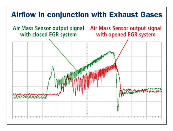
Note: Many a Diesel MAF sensor has been unnecessarily renewed due to a MAF fault code logged – only to find the low air flow was caused by a non-sealing EGR valve.
Please be aware: After renewing the MAF on some vehicles, it may be recommended to perform the MAF sensor learning function after a MAF data reset has been carried out. Refer manufacturer recommendations and procedures.
A typical BT-50 Mazda Diesel procedure after renewing the MAF is shown below:
- Using a suitable scanner perform a MAF sensor data reset procedure to reset the adaption values in the ECU.
- Perform KOEO self-test procedure.
- Turn the ignition switch to OFF position.
- Wait for 5 secs.
- Start the engine.
- Perform KOER self-test procedure.
- Switch ignition OFF.